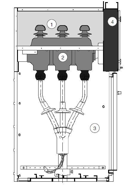
1-busbar chamber
Busbar chamber is located on the top of the switchgear. Main busbars in the busbar chamber are connected together throughout the all switchgear in row.
2-switch chamber
Three load break switches with three working position each are mounted in this chamber. Load break switch enclosure are made of epoxy resin, filled with SF6 gas as insulation medium and with observation window on it. SF6 gas pressure monitor with alarm contact can be added to the switch upon request.
3-cable chamber
This spacious cable chamber is mainly used for cable connection, making single-core or three-core cable connected with the simplest unshielded cable connector. lightning arrester, CT and earthing switch can be also mounted in this chamber. As a standard part, observation window and interlock are located in the chamber door. Cable baseplate is equipped with sealing cover and cable clamp with support frame. The cable baseplate and front door frame can be removed to make cable connection easy and simple.
4-operating mechanism, interlocking mechanism and low voltage control chamber
Low voltage control chamber with interlock can work as control panel as well. Spring operating mechanism with position indicator and mechanical interlock are installed in this chamber, auxiliary contacts, trip coil, emergency trip mechanism, capacitive live display, key lock and motor operating device can be mounted here as well. Low voltage control chamber has space for control circuit, metering device and protection relay. There are two same low voltage control chambers in 750mm wide switchgear, where more accessories can be mouthed.
The whole TUS switchgear can be divided into two parts, upper part and lower part. Upper part includes busbar chamber, load break switch, operating mechanism and low voltage chamber, separated from the lower cable chamber. Thus, equipments in the upper unit can be maintained and renewed easily and safely. The whole upper unit can be changed.
